|
设计简介 |
设计描述:
文档包括:
Word说明书1份,共27页,约15000字
CAD版本图纸,共9张
目 录
1前言 1
2 组合机床总体设计 3
2.1 总体方案设计 3
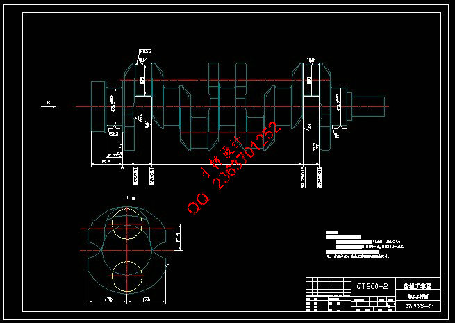
2.2 被加工零件分析 3
2.3 机床结构的确定 3
2.4 本组合机床的特点 4
2.5切削用量的确定 4
2.6刀具结构选择 5
2.7 绘制“三图一卡” 6
3 夹具设计 13
3.1夹具设计的基本要求和步骤 13
3.1.1夹具设计的基本要求 13
3.1.2夹具设计的步骤 13
3.2定位方案的确定 14
3.2.1零件的工艺性分析 14
3.2.2定位方案的论证 14
3.2.3误差分析 15
3.2.4导向装置 17
3.3夹紧方案的确定 17
3.3.1夹紧装置的确定 17
3.3.2夹紧力的确定 18
3.3.3 油缸的选择 20
3.4夹具体的设计 20
4 结论 22
参考文献 23
致 谢 24
附 录 25
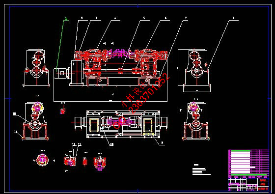
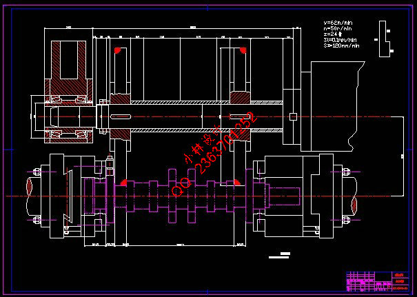
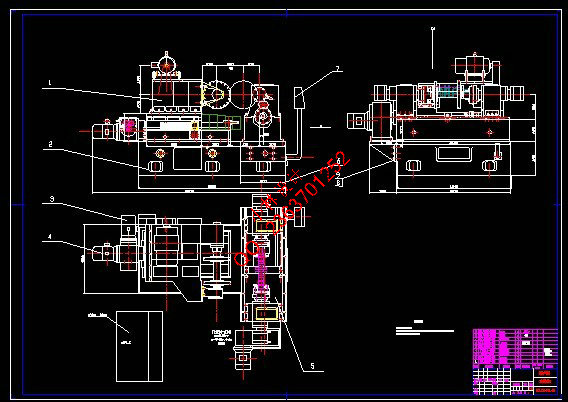
柴油机曲轴连杆轴颈滚切铣床总体和夹具设计
摘要:曲轴中两连杆轴颈的加工是大批量生产的零件。为了提高生产效率,满足被加工零件的精度要求,本课题设计了一台用于加工曲轴中两连杆轴颈的组合机床。本文介绍了该组合机床总体设计和夹具设计的思路,全文共分两个部分。第一部分是总体设计,采用卧式组合机床,考虑的因素有刀具、切削用量、切削力、切削扭矩及切削功率等,通过计算选择主轴直径、外伸尺寸、接杆型号、滑台、动力箱等通用部件,再确定动力部件的工作循环及工作行程,完成机床总体设计。第二部分是夹具设计,通过对被加工零件的全面分析,选用曲轴轴颈定位,夹紧装置采用液压缸夹紧机构,直接夹紧与工件上;夹具体为框架式结构,有良好的刚性,使夹具能长期保持可靠的精度和稳定性。该组合机床不仅能保证加工精度,还能提高加工效率。整个机床布局合理,夹紧可靠,精度较高,使用操作方便,提高了工作效率,达到了设计要求。
关键词:铣床;曲轴;组合机床;夹具;
The design of the overall and jig of the Milling Machine for Crankshaft connecting rod journal in the body of diesel
Abstract: The Processing of the crankshaft connecting rod journal is made for large mass production. In order to enhance the production efficiency and meet the precision requested of the components processed, the topic is produced for designing a combined machine-tool, which is used to processing the crankshaft connecting rod journal. The design was introduced of the overall and jig of the combined machine-tool and the topic consists of two parts. The first part is overall design, Combination of the use of horizontal machines, considering such factors as tool, cutting parameter, cutting force, cutting torque and cutting power, and so on. Thus common parts such as sliding table, the power box and so on, were choused by calculating spindle diameter, and the extend sizes , the link-pole model. Then the operating cycle and the distance were determined. Thus the overall design was completed. Finally, the technological drawing was figured out of the part which need to be manufactured, the general drawing of modular machine tool, and drawing of cutter display and the efficiency card of manufacture. The second part is the jig design, having analyzed the work piece, selected journal crankshaft position ,the clamp uses the Hydraulic pressure device, it directly presses on the work piece, the jig-body utilize the frame structure, possess fine rigidity, causes the jig to maintain good long-term precision. This combined machine-tool not only has guaranteed the drill hole precision efficiency. The laying out of the machine-tool is reasonable, the location of work piece is reliably, the accuracy is high, the operation is easy, enhanced the working efficiency, and meet with the design request well.
Key words:Milling Machine ;Crankshaft; Modular machine tool; Jig
|