|
设计简介 |
设计描述:
文档包括:
word说明书一份,共36页,约15000字
CAD版本图纸,共5张
过程卡一份
目 录
摘 要 II
Abstract III
第1章 绪论 1
1.1机床夹具概述 1
1.1.1机床夹具 1
1.1.2机床夹具的功能 1
1.1.3机床夹具在机械加工中的作用 1
1.2机床夹具的发展趋势 2
1.2.1机床夹具的现状 2
1.2.2现代机床夹具的发展方向 3
第2章 工艺规程设计 4
2.1 零件的分析 4
2.1.1零件的作用 4
2.1.2零件的工艺分析 4
2.2毛坏的选择 4
2.3工艺路线的拟定 4
2.3.1定位基准的选择 4
2.3.2拟定工艺路线 5
2.4加工余量的确定及工序尺寸的计算 6
2.4.1毛坏余量 6
2.4.2泵体各平面加工工序余量 7
2.4.3内孔φ50H7加工工序余量 8
2.4.4内孔φ42H7加工工序余量 8
第3章 切削用量及工时的确定 11
3.1切削用量及机械加工时间的计算 11
3.2辅助时间的确定 23
第4章 车φ30H7孔的夹具设计 26
4.1 定位基准的选择 26
4.2 定位误差分析与计算 26
4.2.1影响加工精度的因素 26
4.2.2 保证加工精度的条件 27
第5章 钻3×M6孔的夹具设计 28
5.1 定位基准的选择 28
5.2 定位误差分析与计算 28
5.2.1影响加工精度的因素 28
5.2.2 保证加工精度的条件 29
第6章 结论 30
参考文献 31
英文翻译 32
摘 要
在机械制造的机械加工、检验、装配、焊接和热处理等冷热工艺过程中,使用着大量的夹具,用以安装加工对象,使之占有正确的位置,以保证零件和产品的质量,并提高生产效率。
在机床上加工工件时,为了保证加工精度,必须正确安装工件,使其相对机床切削成形运动和刀具占有正确的位置,这一过程称为“定位”。为了不因受切削力、惯性力、重力等外力作用而破坏工件已定的正确位置,还必须对其施加一定的夹紧力,这一过程称为“夹紧”。定位和夹紧的全过程称为“安装”。在机床上用来完成工件安装任务的重要工艺装备,就是各类夹具中应用最为广泛的“机床夹具”。
机床夹具的种类很多,其中,使用范围最广的通用夹具,规格尺寸多已标准化,并且有专业的工厂进行生产。而广泛用于批量生产,专为某工件加工工序服务的专用夹具,则需要各制造厂根据工件加工工艺自行设计制造。因此,专用夹具的设计是一项重要生产准备工作,每一个从事加工工艺的工装设计人员,都应该掌握有关夹具设计的基础知识。
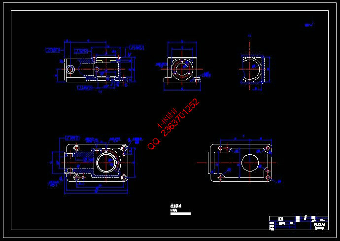
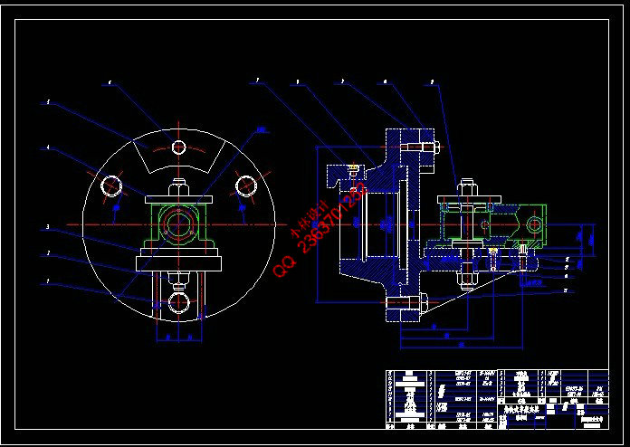
本设计的主要内容是设计钻床夹具,需要对泵体上Φ30的孔进行车削加工及3-M6-7H的螺纹孔进行钻削加工。
机械零件上往往都有各种不同用途和不同精度的孔需要加工。在机械加工中,孔的加工量所占比例较大,其中钻头、扩孔钻、铰刀等定尺寸刀具加工占相当多数。这时,除了要保证孔的尺寸精度外,还要达到孔的位置精度要求。在单件小批量生产中,用划线后找正孔轴线位置方法加工,更因钻头刚性差、易变形,因此生产效率低且精度差。在批量生产中一般都采用钻床夹具,钻床夹具又称钻模,通过钻套引导刀具进行加工可准确地确定刀具与工件之间的相对位置,是钻模的主要特点。
关键词:机械制造,通用夹具,专用夹具,钻床夹具,车床夹具,泵体。
Abstract
At machine manufacture's machine-finishing, the examination, the assembly, the welding and the heat treatment and so on the cold hot technological process, are using the massive jigs, with installs the processing object, enables it to hold the correct position, guaranteed that the components and the product quality, and raises the production efficiency.
Processes the work piece when the engine bed, to guarantee the working accuracy, must install the work piece correctly, causes its relative engine bed cutting builder motion and the cutting tool holds the correct position, this process is called “the localization”. For because of exogenic processes and so on cutting force, force of inertia, gravity is not destroyed the work piece already the correct position which decides, but must exert certain clamping force to it, this process is called “the clamp”. The localization and the clamp entire process is called “the installment”. Uses for on the engine bed to complete the work piece to install the duty the important craft equipment, is in each kind of jig widely applies “the engine bed jig”.
The engine bed jig's type are many, the use scope broadest universal jig, the specification size many have standardized, and has the specialty factory to carry on the production. But widely uses in the volume production, specially unit clamp which serves for some work piece working process, then needs various factories independently to design the manufacture according to the work piece processing craft. Therefore, unit clamp's design is an important production preparatory work, each is engaged in the processing craft the work clothes designers, should grasp the related jig design the elementary knowledge.
The this design's primary coverage designs the drill jig, needs to the pump body on φ30 the hole carries on the lathe work and the 3-M6-7H threaded hole carries on drills truncates the processing.
On the machine parts often has each different use and the different precision hole needs to process. In the machine-finishing, the hole process load accounts for the proportion to be big, the drill bit, the reamer, the reamer and so on decide the size cutting tool processing to occupy quite most. By now, besides must guarantee the hole the size precision, but must achieve the hole the position accuracy requirement. In single unit small batch production, after lineation adjusts the hole spool thread position method processing, because the drill bit rigidity bad, easy to distort, therefore the production efficiency is low, and the precision is bad. Uses the drill jig generally in the volume production, the drill jig calls the jig, through drills the set of guidance cutting tool to carry on the processing to be possible to determine accurately between the cutting tool and the work piece relative position, is the jig main feature.
Key word: Machine manufacture, universal jig, unit clamp, drill jig, lathe fixture, pump body.
|