 |
|


|
设计名称 |
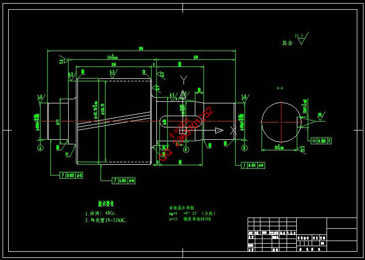
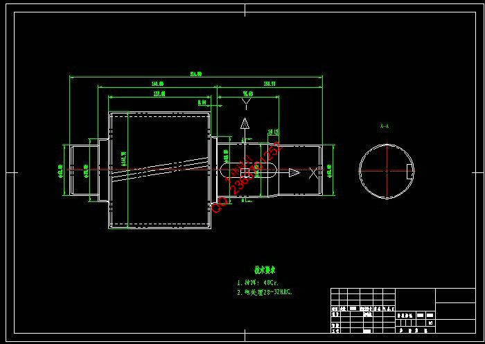
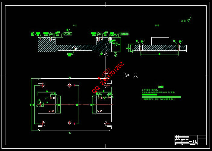
齿轮轴工艺规程及铣键槽的夹具设计 |
 |
|
设计编号 |
W239 | |
|
设计软件 |
AutoCAD, Word | |
|
包含内容 |
见右侧图片 | |
|
说明字数 |
6600字 | |
|
图纸数量 |
见右侧图片 | |
|
推荐指数 |
较高 | |
|
价格: |
价格优惠中 | |
|
整理日期 |
2013.09.26 | |
|
整理人 |
小林 | |
|
购买流程 |
<查看如何购买本站设计> |
|
设计简介 |
设计描述:
文档包括:
一、 设计题目
三、上交材料
四、进度安排 三部分。在工艺设计中要首先对零件进行分析,了解零件的工艺再设计出毛坯的结构,并选择好零件的加 工基准,设计出零件的工艺路线;接着对零件各个工步的工序进行尺寸计算,关键是决定出各个工序的工 艺装备及切削用量;然后进行专用夹具的设计,选择设计出夹具的各个组成部件,如定位元件、夹紧元件 、引导元件、夹具体与机床的连接部件以及其它部件;计算出夹具定位时产生的定位误差,分析夹具结构
的合理性与不足之处,并在以后设计中注意改进。 卡片各一张。首先我们要熟悉零件,题目所给的零件是齿轮轴。了解齿轮轴的作用,接下来根据零件的性 质和零件图上各端面的粗糙度确定毛坯的尺寸和机械加工余量。然后我们再根据定位基准先确定精基准, 后确定粗基准,最后拟定齿轮轴的工艺路线图,制定该工件的夹紧方案,画出夹具装配图,夹具体零件图
。 machining process design, process design and fixture design in three parts. In the design process should first of all parts for analysis, to understand the parts of the process to design the structure of the blank, and select good parts processing base, design parts of the process route; and then the various parts of process dimension calculation, is the key to decide all processes equipment and cutting parameters; then special fixture design, selection and design of a jig for the various components, such as positioning devices, clamping elements, the guide element, clamp and the machine tool connecting parts and other components; calculate fixture is produced when the positioning error of fixture structure,
rationality and deficiency, and later in the design of improved. card and the jig design corresponding to the process card each one. First we should know the part, subject to the parts gear shaft. Understanding the role of the gear shaft, then according to parts of nature and parts of the surface roughness to determine the dimensions of the blank and the machining allowance. We then according to the locating datum to determine the precise basis, after determining the benchmark, to finalize the gear shaft technology roadmap, the formulation of the workpiece clamping scheme, draw the jig assembly
drawing, with specific parts.
|
|
部分图纸 截图 |
    |
|
说明: |
如需了解本设计的具体详细信息请联系本站客服,说明看哪个设计(编号)哪个详细部分,我们将远程或截图给您观看. 机械毕业设计|论文 |

| [要求PR≥2,百度收录≥1000页;联系QQ:178308054] |
Powered by 小林机械资料商城 © 2013-2020 All Rights Reserved. 客服QQ:178308054
喜欢www.xiaolinbysj.com,请告诉你QQ上的5位好友,多谢您的支持! 皖ICP备2021006205号-1
